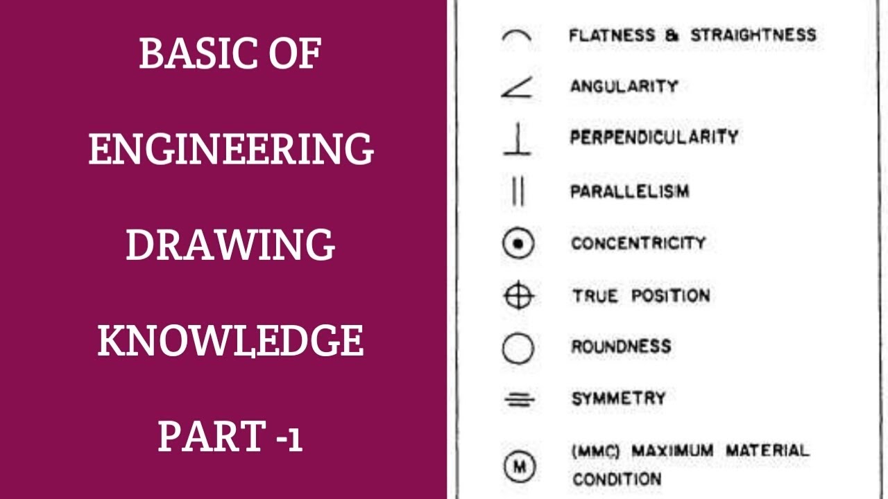
As such, you should check what your company’s preferred abbreviations and symbols are. In addition to these worldwide standards, each design firm has its own set of requirements. You should note that an abbreviation can have different meanings in different categories. Other international engineering standards include ISO, AS (Australia), AFNOR (France), USA (AISI, ASTM, AMS, ANSI, and SAE), AFNOR (France), UNI (Italy), KS (Korea), Germany (DIN and WR), JIS (Japan), SS (Sweden), and BS (UK). ASME handles some specific ones related to mechanical engineering. In the United States, the majority of these terms follow Norms ANSI or ASA. So make sure you understand them well! Are Engineering Drawing Abbreviations and Symbols Standardized?Īs with other engineering terms, abbreviations and symbols are subject to standardization. One typo can lead to serious consequences like making something too heavy. To further aid comprehension of what is on paper, abbreviations and symbols must be accurate. When well used, they result in clean and uncluttered images, allowing the viewer to grasp all important aspects of your design. They should provide all the necessary information to produce a CNC milling part without a hassle.īecause there is no room on your image for text, symbols & abbreviations are relatively less overwhelming. The abbreviations and symbols used must be concise. The design of an engineering drawing is critical. Benefits of Using Abbreviations and Symbols in Engineering Drawings We have prepared an extensive list of engineering drawings abbreviations and symbols for you to reference. If you have found it tough to interpret CNC designs, we’ve got your back! While you may understand the basic terms such as KG and CM, it becomes more difficult when you come across terms such as CYL and EQUI SP. This is where the meanings behind these various pieces come in handy!
BLUEPRINT ABBREVIATIONS AND SYMBOLS FULL
They are full of symbols, abbreviations, and strange phrases that you may not be able to decipher.

However, engineering drawings are complex. You use these drawings for the development and production of a product. To find out about these steps in more detail, check out this guide.CNC design is an integral part of CAD/CAM technology. Define the relationship between components.A degree in Process Engineering or Chemical Engineering.Once the initial P&ID is complete, we like to use Bluebeam Revu for P&ID Markups during online engineering squad checks. These technical drawings can range in complexity and either be hand-drawn or created using specialty CAD software.

It consists of a combination of the process flow datasheet, the mechanical equipment design, and the instrumentation engineering design. Sometimes additional textual explanations are included to convey the required details.Ĭheck out our library to learn more about P&ID symbols and PFD symbols.Ī piping and instrumentation diagram is drawn up at the design stage of an engineering process to model the system.

Technical engineering documents like piping and instrumentationdiagrams (P&IDs) or processflow diagrams (PFDs) consist of pictographic representations, abbreviations, and symbols. To limit errors caused by personal interpretation, engineering drawings and diagrams are governed by standardized language and symbols.

For example, engineering symbols are used in technical drawings to convey the specific geometry and other details about pieces of equipment or components. There are literally hundreds of engineering drawing symbols and they’re used in a variety of ways.
BLUEPRINT ABBREVIATIONS AND SYMBOLS HOW TO
This is the place to learn about engineering symbology, different types of drawings and documents, and how to use modern technology to simplify collaboration. Welcome to our engineering drawing symbols hub.


 0 kommentar(er)
